High Availability WordPress LAMP Stack.
In one of my last little tasks at work, I was asked to eliminate single points of failure in the software and hardware stack without spending a fortune on hardware or software licenses. During the process of ensuring high availability (HA), I realized that many small companies might have similar need, but with more pressing tasks and limited man hours, without a post that talks about all the issues and solutions in one place, many companies and organisations tend to leave single points of failure living with the chance that they’re not going to fail any time soon.
I’ve wanted to write this blog post for a while. After you’ve finished reading this blog post, you should have the knowledge to be able to eliminate the single point of failures in hosting a WordPress website. While I’ve chosen WordPress to be the demonstration of this post, the concepts will work with any apache/mysql LAMP stack software. During the course of this tutorial, I’ll run you through it in two parts. The first part is talking about setting up the physical hosts and topology (using Juniper EX2200 switches, SRX100 border firewall’s and ESXi (free) hypervisors for the software stack.) The second part is talking about setting up the software stack to deliver our LAMP stack in a highly redundant fashion. However what I won't be doing is providing complete configuration examples. Instead, please consider this post as an overview to help enlighten you and link you to more specific information to help you set this up in your own environment.
This blog post is split up in two parts, this first post in the series talks about setting up the network infrastructure, the second talks about setting up the software stack.
Part 1 (physical topology)
- Network overview
- Setting up dual Switches
- Setting up ESXi network cards.
- Setting up SRX border firewall’s.
Part 2 (software stack)
- Nginx load balancing proxy
- Web Servers.
- NFS File Server
- MySQL cluster.
Part 1, Physical Topology
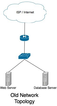
If you’re reading this, I’m guessing your current network topology looks something like
mine used to. You have a single internet connection, single router/firewall, single switch and a bunch of hosts hanging from that switch. In the event of a system failure, your system administrator (me in this case) will have to hop in a cab and rush to the server room to fix the problem.
The goal with this tutorial is to attempt to help your administrators sleep at night. We will eliminate every single point of failure such that in the event of a system outage/failure, the system can self recover with at most a minute of unscheduled down time.
Physical Switches
We’ll be replacing the single switch (in my case, unmanaged old gigabit switch) with a pair of managed switches. Because our bandwidth requirements in this site wasn’t terribly demanding (simple database server, few web, mail servers and the like), a single gigabit Ethernet link to all hosts was all that we required. If you’re in the same boat I was, I can suggest a pair of Juniper EX2200’s. If however, you’re going to be pumping some more bandwidth intensive applications through your network (thus require more then gigabit Ethernet connections to the hosts) or have the need for more then a single VLAN and intra-VLAN routing is required (that’s all outside the scope of this tutorial.) I can strongly recommend you start looking at the EX4200 model switches (set up in a virtual chassis), which can do all your highly available layer 3 IP routing and support multi gigabit Ethernet to your hosts by spanning Ethernet channel across both physical switches.
Active/Passive Switch Design?
Ok, so this heading is a lie, but let me explain. In my switch design with the EX2200’s, I’m using aggregate Ethernet 802.3ad Etherchannel between my two switches. I’ve opted to use 4 physical ports in my 24 port switches (ge-0/0/20 to ge-0/0/23) to give me a 4Gbit/s backbone between them. Obviously with gigabit Ethernet right through the network this isn’t much bandwidth, so the idea is to keep as little data traveling that link as possible (network broadcasts only hopefully!)
First, the following configuration configures the aggregate Ethernet link between the switches:
chassis {
  aggregated-devices {
    ethernet {
      device-count 1;
    }
  }
}

[interfaces]
ge-0/0/20 {
  ether-options {
    802.3ad ae0;
  }
}
ge-0/0/21 {
  ether-options {
    802.3ad ae0;
  }
}
ge-0/0/22 {
  ether-options {
    802.3ad ae0;
  }
}
ge-0/0/23 {
  ether-options {
    802.3ad ae0;
  }
}

ae0 {
  aggregated-ether-options {
    lacp {
      passive;
    }
  }
  unit 0 {
    family ethernet-switching {
      port-mode trunk;
      vlan {
        members all;
      }
    }
  }
}
The only thing you have to watch out for, is that on at least one switch, you set the lacp mode to be active.
Setting up ESXi Network
In my environment, I’m using the free version of ESXi 4.1. I understand that you may wish to be connecting linux hosts directly. If you’re directly connecting linux hosts, I recommend you look at creating a Bonding Adaptor. Thought without the more expensive EX4200’s, we’re best sticking with an active-backup setup and should stick with mode=1.
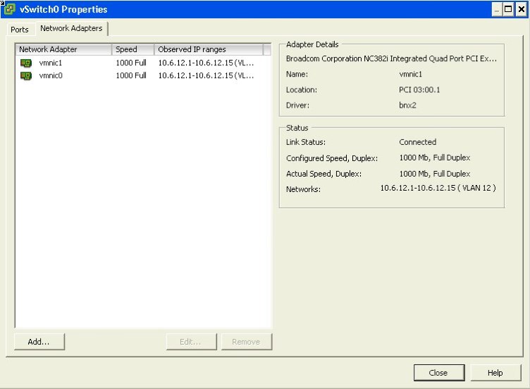
For the ESXi configuration, it’s pretty simple. We connect two NIC’s to the switches. A primary NIC to the primary switch, and a secondary NIC to the secondary switch.
The steps on configuring the vSwitch (virtual switch) are pretty simple. Virtual machines on these ESXi hosts won’t have to do anything special once this setup has been done to take advantage on the physical machines, they’ll just take advantage of our HA network topology.
First, ensure that we have two NIC’s setup on our vSwitch.
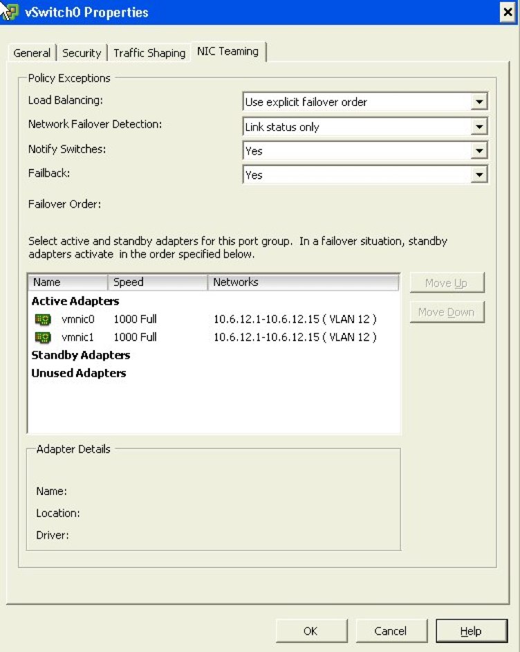
Next, look at the following configuration properties I’ve made to the NIC teaming information. This basic configuration will ensure that when the link on vmnic0 is available (our active switch), it’ll use it. When the link becomes unavailable, it will fail over to vmnic1.
Setting up border firewall’s
The last step we’ve got in our highly available infrastructure here is our border firewall’s. Please bare with me on this section, it is the most complicated and there are a few technologies introduced. If there is something I don’t explain completely, please feel free to leave a comment below and I’ll try and explain it better. I expect you’ll have to jump back and forth between Wikipedia and this article to fully understand what it is we’re doing. Explaining the concepts behind BGP and autonomous systems is beyond the scope of this article.
In my role, I replaced an active/backup GNU based firewall solution (backup being run down to the data center as fast as possible and swap the cables over) with two Juniper SRX100’s configured in an active/passive configuration under a chassis cluster (see SRX100 high availability deployment guide at http://kb.juniper.net/InfoCenter/index?page=content&id=KB15669). We had get a second internet connection installed, then make sure that any one link (or firewall itself) can die and still have the system self recover. There are two major tasks that has to happen to make this gateway highly available. Firstly, our internal network hosts will be using one of these firewall’s as their default gateway. If the link to the primary switch, or the primary firewall itself should die, we still want the network hosts to be able to reach their gateway. We will achieve this with “redundant Ethernet” on the cluster. If you’ve come from the cisco networking world before, picture something like this to be like VRRP for the inside hosts. If the main link fails, the MAC and IP address will float over to the other physical port.
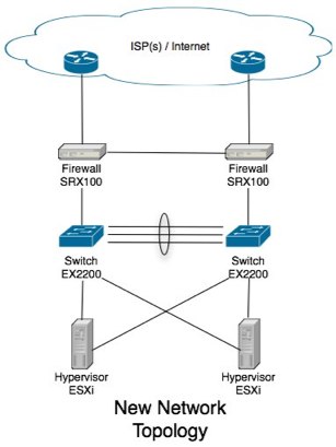
Let me give a bit more detail to our new example network topology here in this example so you can gain a better idea of how these settings work.
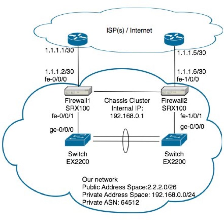
For the internal gateway address to fail over to the other switch should your link off Firewall1 die, You’ll want to make the following configuration
chassis {
  cluster {
    reth-count 2;
    redundancy-group 0 {
      node 0 priority 100;
      node 1 priority 1;
    }
    redundancy-group 1 {
      node 0 priority 254;
      node 1 priority 1;
      preempt;
      interface-monitor {
        fe-0/0/1 weight 255;
        fe-1/0/1 weight 255;
      }
    }
  }
}

interfaces {
  fe-0/0/1 {
    fastether-options {
      redundant-parent reth1;
    }
  }
  fe-1/0/1 {
    fastether-options {
      redundant-parent reth1;
    }
  }
}
You can see redundancy-group 1 is monitoring the local interfaces going back to the switches.
For the dual WAN links, I won’t go into much detail, but you’ll want to ask your ISP for a second internet connection. Some providers offer a cheap link that they only charge you for once you start flowing data over it (sometimes called a Shadow link). This is perfect as you can flow all your traffic through your primary internet connection, then on failure of it, you’ll move your traffic through the secondary. If you wanted complete redundancy, you could apply for a domain independent subnet (has to be a class C to advertise on world BGP tables) and your own ASN. This will let you use two different internet service providers.
In my case, I’m creating a redundant connection using the same ISP, so I’ve asked for a private ASN to be allocated (see http://en.wikipedia.org/wiki/Autonomous_System_(Internet) ).
For a small network such as ours (especially using the small base level SRX’s) you’ll want to ask your provider to advertise only the default route to you. In turn, you’ll advertise your network’s address space on both connections. On the event that a link dies, the BGP peer on the other end no longer receives updates from you and will no longer attempt to route to it.
The following configuration extract shows how we’d configure out SRX firewall’s to peer with our ISP’s routers. Things of note is that our primary link (the one on the left) has a lower metric-out then the shadow link, meaning a lower MED attribute is sent to our ISP and thus inbound traffic will, by preference use the main connection. The preference values under neighbor will determine the preference we will send traffic under that connection for outbound traffic.
routing-options {
  autonomous-system 64512;
}

protocols {
  bgp {
    group ISP {
      metric-out 50;
      local-address 1.1.1.2;
      import ISP-in;
      export ISP-out;
      neighbor 1.1.1.1 {
        preference 170;
        peer-as 123;
      }
    }
    group ISP-shadow {
      metric-out 100;
      local-address 1.1.1.6;
      import ISP-in;
      export ISP-out;
      neighbor 1.1.1.5 {
        preference 180;
        peer-as 123;
      }
    }
  }
}

policy-options {
  policy-statement ISP-in {
    term default-in {
      from {
        route-filter 0.0.0.0/0 exact;
      }
      then accept;
    }
    term block {
      then reject;
    }
  }
  policy-statement ISP-out {
    term tnziPublic {
      from {
        protocol direct;
        route-filter 2.2.2.0/26 exact;
      }
      then accept;
    }
  }
}